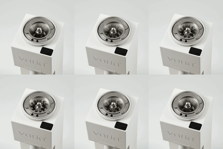
This page is intended to guide Sculptor 078 owners through the disassembly and reassembly process in order to access the internal grind chamber for cleaning. Here you will also learn the internal parts of your grinder and their functions.
Disclaimer: We accept no responsibility for damage caused as a result of disassembling or reassembling your Sculptor 078/s. If your grinder is damaged prior to attempting disassembly and you are trying to diagnose the issue, please contact us first before attempting to diagnose the issue yourself.
Disassembly
Firstly, disconnect the grinder power cable and press the grind button to discharge the grinder fully. Residual charge will reside within the capacitors which will be discharged by pressing the button.
Step 1a: Removing the adjustment mechanism; adjustment dial and locating plate
The adjustment mechanism comprises of three components.
- The adjustment dial
- The locating plate
- The external burr supporting plate
They will be removed in the order given 1, 2 then 3.
The adjustment dial is friction fit, to remove it pull on the dial by gripping the sides and pulling out evenly. This will reveal the locating plate.


Circled - Locating Pin
Unscrew the locating pin slightly. Holding the pin and the body of the grinder, rotate the locating plate anticlockwise until the plate is unthreaded. As you near the end of the threads, slow down and gently remove the plate so as not to scratch the threads. Place aside.
Step 1b: Removing the external burr supporting plate
The external burr supporting plate is secured to the body of the grinder with 6 diametrically opposing H3 (3mm) hex screws. Unscrew each one and set aside. Remove the burr supporting plate by sliding it out evenly. Set down.

Circled - The six 3mm Hex Screws fixing the support plate
Step 2: Removing the external burr plate.
The external burr plate houses the external burr, it is normally pressed against a spring behind it. The external burr supporting plate presses against the burr plate through the freely spinning central section of the supporting plate. This enables the external burr plate to rotate freely.

Circled - Burr suport plate tabs. Arrows show how to rotate the burr plate to free the tabs through the channels
Now that we have removed the supporting plate, the spring pressure is pushing the burr plate against a ridge on the inside of the chamber. To remove the burr plate, lift the metal wire handle between your fingers and push on the burr plate (you will get a feel for the spring resistance), then simultaneously rotate it until the tabs on the outer section of the burr plate are free through the channelsa on the ridge. Then you can slide the burr plate out from the chamber to reveal the fixed inner burr.
Optional Step 2b: Removing the external burr from the burr plate.
Two Philips screws hold the external burr to the burr plate, removing these will allow you to remove the burr itself.

External burr on the burr plate with the two Philips screws removed
Step 3: Removing the inner burr
Self explanatory, there are two Philips screws that fix the inner burr to the chassis of the grinder. Remove these and carefully extract the inner burr by gripping it through the hole and the burr face and gently pull.

Circled - Two Philips screws fixing the inner burr to the chassis
Step 4: Removing the spring and rear bearing assembly.
This is completely optional, but I thought it noteworthy to mention these parts exist as they are loose so if you move the grinder at this stage, they could fall out. At the rear of the grinder you can see the spring. This can be removed using pliers, or by upturning the grinder. By doing this you may cause the bearing assembly to also fall out, so be careful. I must stress that there is no reason to remove these parts at this stage.

Above shows the rear bearing assembly, the spring (not photographed) would be housed over the central motor spindle. The bearing assembly is loosely friction fit into its housing.

Above shows the bearing assembly comprising of the bearing itself and the outer plate. The inner plate has a grooved channel where the ball bearings run along is also loosely fit and can be removed. This bearing assembly allows low friction rotation of the external burr supporting plate against the chassis.

The rear bearing plate is shown here.
Cleaning
At this point take the included brush and air blower and thoroughly dislodge all the grinds you can find inside the grinder, a hoover also works well here. Agitate the burr sets with the brush, don't be afraid to use a higher force on the burr set to clean them up. Clean the burr plate and supporting plate. Be careful with some oiled components such as the motor spindle, the threads on the locating plate and supporting plate, these components require lubrication so do not clean the oil residue from these components.
Reassembly
Step 1: Affixing the inner burr to the grinder
Align the inner burr with the screw holes, the holes are at 9 and 3 O'Clock. Ensure both screws have the same hand tight torque, as soon as you feel resistance on the screwhead, another 1/4 turn will be sufficient.
Step 2: Refitting the burr plate
This can be tricky. Notice first that the burr plate is keyed in two places, firstly the motor spindle and secondly the tabs on the outside of the plate which slide into the two oppositely located channels on the ridge in the grinder.

Slide the burr plate onto the motor spindle and align the tabs with the channels and slide it through. You should feel spring resistance at this point. If you don't and you just feel a hard stop, remove the burr plate and spin the motor spindle very slightly and try again. This is because the spindle would have locked the burr plate in a certain orientation which won't allow the burr plate to reach the spring. Now push against the spring and rotate the burr plate to lock the tabs behind the ridge.

Above shows what the burr plate should look like after it has been pushed through the channels and rotated such that the tab/s are behind the ridge locking it in place
Step 3: Refitting the external burr support plate
Take a look at the support plate, the collar is keyed with four ridges - three on one side and one opposite. Now look at the burr chamber, you will see the four channels that will accept the ridges.

Above: Channels for the support plate
Below: Tabs on the support plate (rear of support plate shown here, this face inserts into the chamber)

Align these up and slide the support plate fully in. Now screw all 6 hex screws in almost tight. Here's the important bit, screw the hex screws tight in opposites. Tighten one, then go to the opposite screw and tighten, then another pair. This is to maintain optimal alignment. The screws need only be tightened 1/4 a turn after you feel resistance.
[The act of tightening the screws pushes the support plate against the burr plate against the spring and releases the burr plate tabs away from the ridge so that it can freely rotate. The support plate is connected to the burr plate via a bearing in the centre of the support plate. The rubber ring shown on the support plate is the contact point.]
Step 4: Refitting the locating plate and adjustment dial
Align the locating plate threads with the support plate threads and screw the locating plate clockwise, using the locating pin to spin. Screw all the way until you hear clicks and keep going. When you start to feel a higher resistance, and the '0' position marker has gone past 3 o'clock, rewind and unscrew until the '0' marker is aligned at 3 o'clock. Then tighten the locating pin at 12 o'clock. What this does is set the '0' position.

Alignment of the 0 position at 3 o'clock and locating pin at 12 o'clock. The locating plate was positioned this way after tightening as far as possible and then loosening anticlockwise to this position.
Then take the adjustment dial, align 0 at 3 o'clock and press fit. The hole for the pin is located at 15, so the correct orientation is 0 at 3 o'clock and 15 at 12 o'clock.
Your grinder is now reassembled, cleaned and calibrated. We would recommend cleaning your grinder every month or so if you continuously use it. The burrs are crushing burrs so oil build up in the crevices of the teeth will happen over time.
Any questions, we're always free on the live chat here or drop an email and we'd be more than happy to help you out!

